Monday, October 4, 2010

New z-axis, part 2

The new z-axis is going through some tests before the 3D printer will be upgraded. See pictures of the testbed in previous post. When letting the stepper motor run, it seemed that the belt tried to escape from the pulley which is on the stepper motor when turning in one direction. This was not foreseen and would be disastrous if it would happen during a print. To make sure that the belt can not run off the pulley, an additional idler with large washers is mounted so that the belt will be forced back to the middle of the pulley should it try to escape. Fortunately there was some space right next to the motor where an extra hole could be drilled for the idler. It seems to work fine now as can be seen in this short video:


One reason why the belt was trying to move down the pulley is that the motor was not mounted 100% straight. It seems the PLA was warped a bit more than I thought initially. The motor is now mounted straight by adding 2 very thin washers between the PLA plaform and the stepper motor on one side. The additional idler will be a useful saveguard anyway; it also changes the path of the belt slightly so that the belt has more contact with the pulley, reducing the chance the belt would skip.

I still want to do some more tests with the threaded rods in place before I upgrade the printer. More on that later. Also, the y-axis needs to be lifted a bit to allow the z-belt to move under it.

New z-axis

The part which work the least well currently is the motor drive of the z-axis. The z-axis is constructed using 2 motors, one on each side. Since the construction is not completely straight, the vertical threaded rods wobble a bit. The threaded rods are also made of cheap galvanized iron and small bits of metal are falling off when in use. Forgetting to lubricate the threaded rods regularly causes one side of the z-axis to stop turning causing some damage to the system. This setup was the easiest to construct in the beginning when I did not have a 3D printer available to create parts. Since upgrading the extruder, the z-axis construction creates a bigger problem; the new extruder does not stick out from under the x-axis quite as much as the old one, meaning the z-axis needs to be lowered further. But the lower the x-axis is moved the worse the misalignment for the threaded rods starts to cause friction. To be able to print without lowering the extruder too much, a temporary solution was to increase the height of the print bed using a square piece of foam some 3 cm thick (visible in the picture in this post). This works, I printed all the PLA on it so far, but the print bed is not as stable as it used to be. So time to improve it.

I bought the mendel timing belts a while back and printed z-pulleys for the threaded rods. Since I do not have a mendel frame in the printer I needed to create a base for the z-axis threaded rods and a single motor so they can be mounted on the wooden base of the printer.

On one side only a support for a ball bearing is needed which has space for the z-pulley under it. It looks like this:


On the other side the same construction is needed, but in addition a stepper motor needs to be mounted and an idler wheel which can be moved to adjust the belt tension.  It was printed upside down like this:


This was the biggest object which I printed so far. It took 4 hours to print it and measures 6 by 12.5 cm. Even PLA starts to warp a bit at this size, but the warping is small enough that it the object is fully functional.

Before this setup is going to be integrated with the printer I want to make sure it is reliable, so I first mounted it on a piece of scrap wood to run some tests. The hex bolts temporarily take the place of the vertical threaded rods.


The testing has not been finished. More information about the success (or failure) later.

Sunday, October 3, 2010

Legs

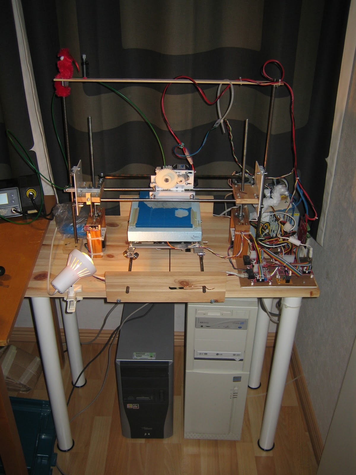
The 3D printer is built on a plank of wood of  40 by 80 cm This gives ample space to place electronics, power supply etc. on the base and have everything easily accessible. It did take a lot of space on my worktable so it had to go somewhere else. Rather than getting another table in the room, I decided to mount legs under the base and make a table out of the printer. The legs are easily removed if needed for transport.


Wednesday, September 22, 2010

Repairs around the apartment

No major developments on the printer this time, but the printer has been useful for a couple of repairs around the apartment. Don't ever get a 3D printer just for repair purposes, but if you happen to have one of them, it can be very handy.

The support of a part of the window shutters broke; it took 2 iterations, but now there is a piece which is as good as the old one.


A glass shower cabin system turned out to be a bit flimsy. It has one support bar consisting of 2 aluminium tubes which should fit with a plastic ring (grey in the picture). Since the ring was a bit too thin, the inner tube could move inside the outer tube too much. Two additional plastic rings were printed to make the tubes fit perfectly and make the system much stronger than the original. You can see the ring on the right needed some sanding to get it to fit. The ring on the left was printed later with a slightly smaller outside radius as learned from the first ring. The picture was taken when the rings where almost ready to go inside the outer tube where they won't be visible anymore.


New shelves in the kitchen cupboard above the sink turned out to be more than one centimeter wider than the old ones, making the support pieces useless since they required small nails to be driven into the wood too close to the edge. Designing new support pieces did not take long and printing four pieces at a time produced  new supports in about an hour. The pieces are screwed at an angle of about 45 degrees to make screws accessible with a screw driver, but keep the head of the screw completely inside the plastic in a neat way. You can see that this is printed with the new wade type extruder which is still not controlled by the printer software, meaning that there are way more plastic strings between the 4 pieces than necessary which needed some sanding; fixing this is on the to-do list... The final result is nice; it could have been printed in white ABS easily, but using green PLA makes the cupboard more interesting! A total of 20 pieces were printed for 5 shelves.


Finally some small pieces of the printer which where printed a while back already. The power supply unit is mounted on the base of the printer, which is is a piece of wood. A metal strap around it will keep it from falling off, but it won't keep it from moving. Four plastic corner blocks where printed which keep the power supply a bit above the base and prevent it from shifting.


Next time more development work on the printer.

Wednesday, September 8, 2010

Mini-stepping and PLA

The extruder is working, but the quick and dirty solution to use full steps for the extruder stepper motor was causing some unwanted vibration, see previous post. The stepper motor driver IC TCA3727 (datasheet) is actually capable of full, half, quarter and "mini" stepping. Each phase of the stepper motor can be fed with 3 different current levels ("hold", "set" and "accelerate") and using all those different current levels between full steps will allow for a total of 24 phases in one complete cycle (full stepping uses 4 phases per cycle). Since all the wires controlling the current where already connected to the arduino only software needed to be changed. The "mini steps" are implemented now and the vibration is much less and the motor runs much smoother.

There is still no control of the extrusion motor, I start the motor manually just before a printing cycle and stop it when it is done printing. For some objects this is no problem, they come out fine, like this one:


Other objects which consist of layers in which there are separated "islands" will have bigger problems as thin threads of plastic will be formed when the extruder moves from "island" to "island". This is such an area:


In general PLA is working very well. The smell is much less, I have not found any warping of objects so far and the translucent nature gives for pretty objects. PLA is behaving differently than ABS. PLA is much harder when cold, but is very soft when an object is still warm. For small objects it is necessary to let them cool down before removing them from the base to avoid deforming them in the process. One type of object which is causing a problem here is a very thin tall object. Since the lower layers stay a bit soft, the friction of the extruder will cause the object to move with the extruder and gets ruined; this was supposed to be a straight, vertical cylinder about 5 mm in diameter.


I use the blue painter's tape on the base which is recommended widely and I find that very easy to use. The objects seem to adhere well to the tape, but the tape can be peeled of reasonable well.

I have not figured out yet what the best height is for the first layer. If the height is too high, the first layer will be messed up. When it is too low the first layer will be squeezed down, become super flat because of that, but it becomes a bit wider than the object should be. Check out the lowest layer of this object, it is on top in this picture as I turned it upside down. This is the same object pictured above from the top side.


As always, comments and questions welcomed.

Monday, September 6, 2010

New extruder, continued.

As promised some details about the new extruder.

The new extruder as described in a previous post was connected to a new x-carriage using L-shaped aluminium strips and m3 bolts. The x-carriage is the same as the x-carriage made for the makerbot MK4 extruder. I decided to keep the old carriage with MK4 extruder untouched to be able to switch back an forth between extruders easily by just replacing the whole x-carriage. Extruders not being the most reliable part of the 3D printers...
I used a new nozzle and PTFE insulator from mendel-parts.com. Though this nozzle and insulator are meant to be used as in standard mendel fashion (glued at the insulator), I decided to make the construction a bit stronger. The filament is pushed down with quite a bit of force into the nozzle and when the insulator is getting warm it may fail. To prevent the downward force to be taken up by the insulator most modern extruders have some kind of support connecting the nozzle to the rest of the extruder above the insulator. I used a thinned M6 nut on the nozzle and stip of alumium attached by 2 long m3 bolts to protect the insulator.

The aluminium strip is not ideal as it conducts heat too well. The contact area between the nut and the aluminium is kept as small as possible and there is a bit of kapton tape in between; the nozzle does not touch the aluminium.  A new design for the mendel extruder which can be found in the wiki uses a piece of PEEK, but I did not have that available. Below the aluminium strip a short part of the nozzle is left to put the nichrome wire around and to attach a thermistor. All is electrically isolated with kapton tape. As I did not have proper heat insulation around the hot end of the extruder like in the MK4 extruder and the metal strip is leaking some heat, I see it takes a bit longer for the extruder to warm up properly and the temperature seems to vary more than it used to. This does not seem to hurt the operation and the extruder is working fine. A hose clamp around the insulator is an additional bit of protection, not sure if that is really needed, but it probably won't hurt.

The stepper motor is controlled by a TCA3727 integrated circuit via a separate arduino board. The TCA3727 is quite old and better alternatives can be found, but is works fine. A quick-and-dirty program was written to make the motor turn at a constant speed using full steps. The circuit allows for quarter and eighth step but I did not think that would be necessary; that was a wrong, because while the stepper motor turns at the right speed, it vibrates horribly. Especially since the x-carriage is pulled down by gravity only (no ball bearings under the horizontal metal rods), one full step lifts the carriage an invisible fraction everytime before it falls back. When PLA is extruded in the air and left to flow down, it is visible that the extrusion in not constant but it is a bit thicker for each step. Some more software should fix this later.

The extrusion motor control is not integrated with the rest of the electronics or the rest of the software. I manually start extrusion and the printer software is still sending signals to the MK4 gearmotor, though that is not connected anymore. This works surprisingly well. Of course there are ugly plastic lines from head movements where the extrusion should be off but isn't here an there, but depending on the object to be printed these could be tolerated. Of course this will be fixed later, having precise control over the extruder was one of the reasons for building a stepper controlled extruder in the first place.

So far I used the MK4 extruder only with ABS plastic. The pulley which is used to get a grip on the plastic filament has "teeth" which are quite wide. The ABS was clearly stretched and clear marks of the pulley are visible on the filament. Since PLA plastic is much harder (when cold) than ABS. I did not even try it, though some people did get it to work. The new extruder is using many more, but much smaller "teeth" to get grip on the filament. PLA has the advantage of warping much less allowing larger objects to be made. The largest object made so far with ABS is the big gear on the new extruder. It too is warped a bit, but it is just "flat enough" to work.


Summarizing things that can be improved still on the extruder:
- extruder connected with 2 aluminium strips on each side, a better design should allow that to be just one part
- motor control from 3D printing software. I currently use replicatorG but I have not found how that can be integrated with a stepper controller yet, maybe it is time to switch over to the FiveD reprap software which has inbuild extruder stepper motor control.
- Wiring should be fixed.
- 8th stepping to be implemented.

The extruder works though and printed without issues for more than 2.5 hours in a row on a single object.

Sunday, September 5, 2010

New extruder's first steps.

The new extruder is working! It is not ready yet, but I can show the first picture.

The extruder is mounted on a new carriage built in the same way as the previous carriage. I would like to improve it later still, because I needed 2 sets of aluminium strips when one should have been enough, but it works ok like this. The extruder is kept down by gravity only.

The green key is printed in green PLA. More information to follow.