The problem with the moiré pattern which was visible in the prints last time has been fixed. I got several suggestions about possible causes. The one I focused on first was the possibly that the pulleys of the wires which are moving the "axes" up and down where not round. I got better quality pulleys, but this did not solve the problem. While trying to debug the issue I noticed that when the printer was running really slow, the sound of the printer was changing. I vaguely remembered a blog post about problems with the stepper motor drivers somewhere and I found the problem. It turns out the current which is running through the motor is too small to actually get the motor to move in certain phases of a rotation. The solution was quite simple: increase the current through the motor. The current through the motor is adjustable with a tiny potentiometer on the stepper driver board. The previous setting was so that the stepper motor would have just enough current to not loose any steps (full steps). I now increased the current so that it is enough to drive the motor in all phases (all 16 microsteps) of a full step. The blog post I found the information in is here: hydraraptor Stepstruck.
The print quality increased a lot:
Wednesday, April 2, 2014
Saturday, December 14, 2013
Moiré pattern
There are some artifacts showing up in the prints of the delta printer. Depending on the shape of the object they are more or less visible. I printed a flat vertical object, 80 x 80 mm, to be able to see the effect properly:
Most of the time this is no problem, but there may be some ways to tune the printer to minimize the deviations.
Interesting discussion going on on the google forums here.
Most of the time this is no problem, but there may be some ways to tune the printer to minimize the deviations.
Interesting discussion going on on the google forums here.
Monday, December 9, 2013
Hot-end clogged
In the new delta printer I use this hot-end from RepRapWorld. I have used exactly the same hot-end in the previous printer and it has worked very well there. The hot-end should be made according to these specifications.
When pushing the filament through by hand before mounting the bowden cable, I noticed there was a lot of friction. When printing the first objects the extruder motor started to skip steps, or the hobbed bolt would slip the filament back before the filament got stuck completely and no more plastic was coming out.
When removing the plastic from the extruder, the plug looked like this:
There are 2 things wrong here: there is a bit of a flat end which is larger than the 0.5 mm hole where the molten plastic leaves the hot-end, and the angle of the top of the plug seems to be too big. The specifications state a 90 degree angle drill bit should be used for the inside and there should not be a flat area at the end. This is part of the original specifications:
I don't have a proper 90 degree 3.5 mm drill bit and my local shop did not have one either. So I modified a normal 120 degree drill bit and drilled the hole a fraction of a mm deeper. After this, the plastic is flowing better. I would still like to have it flow faster, but at least now I manage to keep the printer running for more than an hour. The maximum speed is about 40 mm/second, I think on the other printer I manage to get more, but I don't have a reference figure at the moment.
When pushing the filament through by hand before mounting the bowden cable, I noticed there was a lot of friction. When printing the first objects the extruder motor started to skip steps, or the hobbed bolt would slip the filament back before the filament got stuck completely and no more plastic was coming out.
When removing the plastic from the extruder, the plug looked like this:
There are 2 things wrong here: there is a bit of a flat end which is larger than the 0.5 mm hole where the molten plastic leaves the hot-end, and the angle of the top of the plug seems to be too big. The specifications state a 90 degree angle drill bit should be used for the inside and there should not be a flat area at the end. This is part of the original specifications:
I don't have a proper 90 degree 3.5 mm drill bit and my local shop did not have one either. So I modified a normal 120 degree drill bit and drilled the hole a fraction of a mm deeper. After this, the plastic is flowing better. I would still like to have it flow faster, but at least now I manage to keep the printer running for more than an hour. The maximum speed is about 40 mm/second, I think on the other printer I manage to get more, but I don't have a reference figure at the moment.
Delta printer progress 2
Since last time, I added carbon fiber reinforced rods between the ball joints on the carriages and the ball joints on the extruder platform.
I also added some switches to each X, Y and Z "corner" which will be used to home the extruder. The standard homing procedure which is used, is to quickly move each carriage over the axis up until the switch is closed. It then moves down a few millimeters and moves up slowly until the switch is closed again.
The switch at the top:
You can see the homing procedure, the switch and the carbon fiber rods in this video:
The motor part is here:
The parts are borrowed from RichRap's 3DR printer which in turn is based on the Greg's Wade extruder.
The first half of the hot-end is mounted on the carriage here:
The first print of the printer failed, more on that later. But the printer is working as can be seen in this video:
Sunday, November 24, 2013
Delta printer progress
Progress is slow, but steady. Currently the printer looks like this:
Initially I had different brackets connecting the 2 linear bearing next to each other. I was disappointed with how (not so) smooth this was running.
With limited tools and space available, I don't always manage to get everything 100% straight or holes drilled in exactly the right spot. This easily leads to over-constrained mechanisms: the top and bottom planks try to keep the vertical rods at 49 mm apart while the plastic bracket tries to keep them at 50 mm apart.
In the original Sells-Mendel printer, proper design was used to make sure that no mechanisms were over-constrained. Somehow nowadays most printers seem to be produced precise enough to allow for parallel linear bearings without causing too much pain.
I decided to modify the bracket to make sure only one linear bearing was used for guiding the bracket in 2 dimensions and the other bearing is only used to make sure the bracket can not turn around the first rod. This means the second linear bearing needs to be able to move slightly sideways and be allowed to be slightly non-parallel. By attaching the bearing with only a single cable tie and creating a small "bump" where the bearing is touching the bracket, enough free movement was achieved. The bracket looks like this (red is old, white is new):
This seems to work much better, installed the bracket looks like this:
The previous picture also shows the idler wheel bracket at the bottom of the rods which is used to guide the spectra wire (0.46 mm, 55 kg breaking strengh) back up to the stepper motor.
I have started on the electronics part as well. I use the Megatronics 2.0 board from www.reprapworld.com and so far it seems to work fine.
Initially I had different brackets connecting the 2 linear bearing next to each other. I was disappointed with how (not so) smooth this was running.
With limited tools and space available, I don't always manage to get everything 100% straight or holes drilled in exactly the right spot. This easily leads to over-constrained mechanisms: the top and bottom planks try to keep the vertical rods at 49 mm apart while the plastic bracket tries to keep them at 50 mm apart.
In the original Sells-Mendel printer, proper design was used to make sure that no mechanisms were over-constrained. Somehow nowadays most printers seem to be produced precise enough to allow for parallel linear bearings without causing too much pain.
I decided to modify the bracket to make sure only one linear bearing was used for guiding the bracket in 2 dimensions and the other bearing is only used to make sure the bracket can not turn around the first rod. This means the second linear bearing needs to be able to move slightly sideways and be allowed to be slightly non-parallel. By attaching the bearing with only a single cable tie and creating a small "bump" where the bearing is touching the bracket, enough free movement was achieved. The bracket looks like this (red is old, white is new):
This seems to work much better, installed the bracket looks like this:
The previous picture also shows the idler wheel bracket at the bottom of the rods which is used to guide the spectra wire (0.46 mm, 55 kg breaking strengh) back up to the stepper motor.
I have started on the electronics part as well. I use the Megatronics 2.0 board from www.reprapworld.com and so far it seems to work fine.
Sunday, September 22, 2013
Delta printer
The current printer is working, but it will be difficult to improve the quality of the prints without doing extensive modifications. Delta printers are becoming more common and I decided to start building a printer of this type.
A very nice delta printer recently made by Richrap looks very good and I will be borowing some ideas from there. I will however not use the massive bottom and top printed parts but use MDF boards which will be quicker to build and will allow modifications and extensions later on.
To get the printer body simple but still stable I decided to use 22 mm MDF and M14 (!) threaded rods to keep them in place. Since the threaded rods are sold in lengths of one meter, I needed to buy full lengths for each column. Instead of cutting them to length, I decided to keep the rest of the rods as legs. This printer is now at a pretty good height and does not need any table space.
To make sure the holes for the threaded and the smooth rods (8 mm) are in the correct place so that all the rods will be parallel, I temporarily fixed the 2 boards to each other with screws before drilling the holes:
After drilling it only took a few minutes to have the frame of the printer ready:
The first printed parts are the carriages which connect the 2 linear bearings on each pair of smooth rods and the arms to the extruder. I modified the carriage from Richrap just to fit the bigger bearings and the different spacing between the rods:
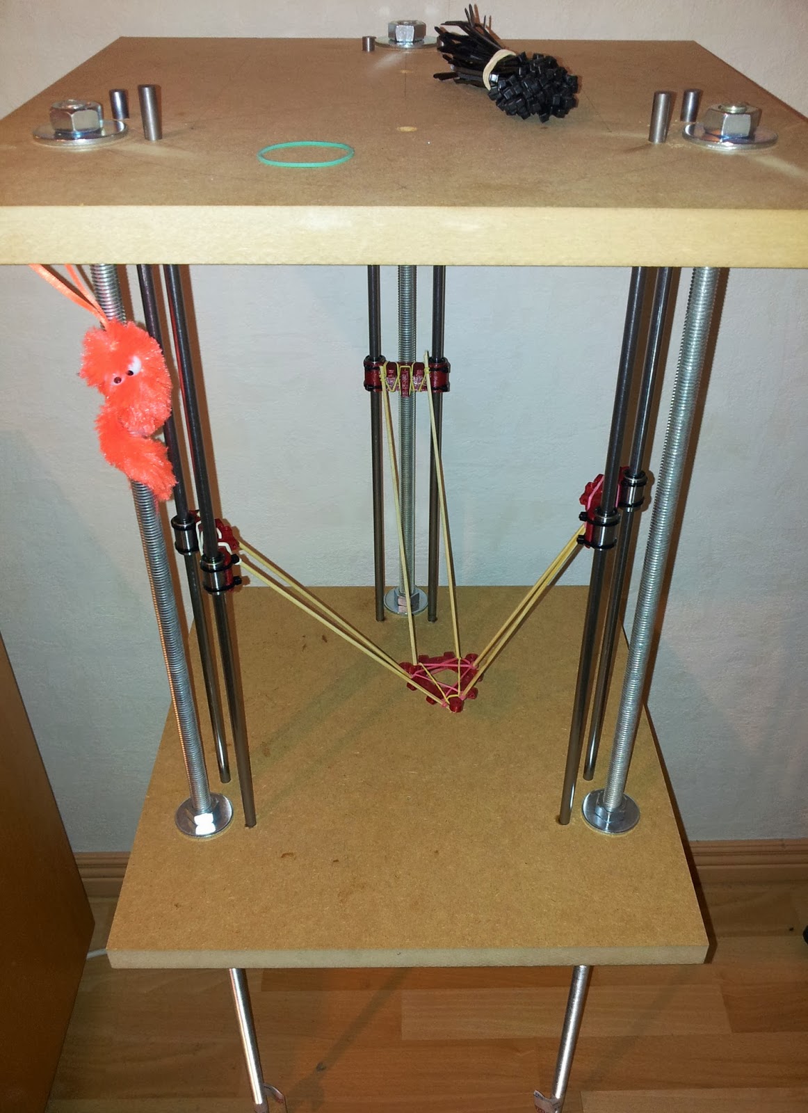
To see what the reach of the arm is going to be, I fixed some wooden rods with rubber bands between the extruder base and the 3 carriages. A lot of work is still needed, but it starts to look like a delta printer!
A very nice delta printer recently made by Richrap looks very good and I will be borowing some ideas from there. I will however not use the massive bottom and top printed parts but use MDF boards which will be quicker to build and will allow modifications and extensions later on.
To get the printer body simple but still stable I decided to use 22 mm MDF and M14 (!) threaded rods to keep them in place. Since the threaded rods are sold in lengths of one meter, I needed to buy full lengths for each column. Instead of cutting them to length, I decided to keep the rest of the rods as legs. This printer is now at a pretty good height and does not need any table space.
To make sure the holes for the threaded and the smooth rods (8 mm) are in the correct place so that all the rods will be parallel, I temporarily fixed the 2 boards to each other with screws before drilling the holes:
After drilling it only took a few minutes to have the frame of the printer ready:
The first printed parts are the carriages which connect the 2 linear bearings on each pair of smooth rods and the arms to the extruder. I modified the carriage from Richrap just to fit the bigger bearings and the different spacing between the rods:
To see what the reach of the arm is going to be, I fixed some wooden rods with rubber bands between the extruder base and the 3 carriages. A lot of work is still needed, but it starts to look like a delta printer!
Monday, April 8, 2013
Customizable NFC Keyfob
More and more phones can read NFC tags nowadays.
Samsung and Sony are selling (Smart) Tags and NFC stickers. The tags are quite a lot more expensive than the stickers. You can print this NFC keyfob and put the sticker inside.
This video gives some background into NFC and NFC smart tags:
I created a customizer script so you can define the size and shape of the tag for your stickers. Details at thingiverse:
I used these stickers:
Subscribe to:
Posts (Atom)