Sunday, December 19, 2010

3D print from start to finish

Though similar videos exist on the internet, I wanted to document the full printing cycle of my repstrap printer. A 40 minute print condensed into 4 minutes:


The final object is here:


From the video a few issues with printing can be seen which I hope to work on improving in the future:
  • Speed. The printer is not very fast. Increasing the speed is certainly possible, but I need to make sure I have enough spare parts to repair the printer if I break it before I attempt to do that.
  • PLA dripping out after the extruder motor stops. It can be observed that after the test extrusion, when I have removed the extruded plastic hanging from the nozzle, that melted PLA drips out. This results in blobs on printed objects which should not be necessary.
  • The first few centimeters of printing did not work. This could be related to the previous issue: plastic has been dripping out and pressure has to be build up before there is a constant flow of plastic.

This object can be found at thingiverse here and is my favorite test object which has been printed quite a few times in different materials and different sizes.

Wednesday, December 1, 2010

What is this?

I printed this thing:


Documented on thingiverse: here.

Sunday, November 21, 2010

Filament spool

With the printer becoming more and more reliable, longer prints are made and a filament spool was needed. The spool was made using a metal tube with printed PLA endpoints glued to it and some cardboard. The filament is kept resting on some M6 threaded rods.


The spool is hanging in a huxley frame. I may replace the frame with something else if I need to finnish the huxley, for now the rapstrap is working fine.

Today a 2 hour print and a 5 hour print were done without any help in the middle. Should order more PLA now...

Tuesday, November 2, 2010

Z opto endstop

The new z-axis is very stable and I am confident enough to take the z-axis opto endstop into use for calibrating the height automatically at the beginning of a print. A very simple bracket to hold the opto endstop was printed and fixed to a vertical rod. The endstop is mounted with bolts with springs to allow for easy calibration. Three nuts are trapped in the plastic. The bracket looks like this:


The final endstop installed looks like this:


The printing procedure now is to set the extruder in the middle of the area where an object should be printed, with height close to zero (0-2 cm high). The extruder than will be lowered 2 cm, but the movement will stop when the opto endstop is activated. This is the point where the height is calibrated to zero and the extruder can move up 2 cm to warm up and do a test extrusion.

Sunday, October 31, 2010

Extruder crontol

The original makerbot MK4 extruder worked well until it broke, but like most extruders the starting and stopping of the plastic flow was not very accurate. When printing simple objects this is not a problem, a few loose strings here or there are easily removed with a sharp knife. The extruder motor did reverse a bit after extruding to try to reduce oozing out of plastic, but the gear motor was not really suited for that purpose. I read that now in the the latest version of ReplicatorG the reversing is not switched on by default to reduce the strain on the motor. One of the reasons for building the new extruder based on Wades's design a while back was exactly the extra control over the flow of plastic which a stepper motor would provide. The new extruder has been working fine so far, but one thing I had not done yet: the new extruder was running all the time using a separate Arduino processor and was not controlled at all by the printing software. This works ok, but of course it produces a large amount of strings between the different parts of a model, like in this part of the new Z axis support:


The part is fine after some cleanup with a knife as can be seen here.

The current standard software for the mendel includes support for a stepper motor in the extruder, but the control circuit which is used by default is a double motor steering on the extruder mother board which is not very good for this purpose. I think there are several pieces of software being developped which look promising for the near future (e.g. here), but I don't have a standard solution right now. So in order to get control over my extruder now, I hooked up the output of the extruder mother board which used to go to the MK4 extruder gear motor to my arduino board which is controlling my stepper motor. Since the extruder board is sending 12V signals I reduced the signal voltage with some diodes and resistors so it is safe to connect to the input of the arduino.


The arduino will now detect the extruder motor state from the 2 signals and determine if the motor should go forward, backward or stop. There are some limitations, but it works!

I printed this nice puzzle, a Philippe Dubois burr from thingiverse, which consists of 6 different parts. All parts where printed at the same time and the extruder stopped and started during moves between the different parts for each layer (first layer 1 for all parts is printed, then layer 2 for all parts etc.). As you can see the amount of strings is very little; strings are not completely gone, but no comparison to the z-axis picture above!


The puzzle looks like this when assembled:


The puzzle is much more difficult than I imaged. There is a good website describing the different forms of the puzzle and also includes animations of the solutions. This particular puzzle is what is described on the website as a level 6.4 burr puzzle. This means it takes 6 (!) moves before you can remove the first piece, after that it takes 4 moves before you can remove the second piece. After this the other pieces fall apart.

Thursday, October 28, 2010

Contest won, glow-in-the-dark ABS on the way!

A few designs in the previous blog posting were submitted to the Makerbot halloween contest. This week the result was published and the bat mobile design was one of the winners! Makerbot actually choose 2 winners, the other winning design was this great spiderweb.

The price for the contest is a roll of glow-in-the-dark ABS plastic from the makerbot store which is on the way to Finland now.
The Bat mobile will definitely be printed again in this new ABS and I'll post some pictures of the bat mobile with the lights off.

For now just a fresh picture of one of the bats with the lights on:


The bat was created using tricks described in the wiki of EvilMadScientist here, originally intended for the eggbot. One final step in the creation process is the conversion of an SVG file of the source image into gcode. For this I wrote a little script which I had intended to document later. A newer version of skeinforge however apparently has now a built-in way to import SVG files and create gcode from that so I won't be working on the script anymore (I have not tried the new version yet). Of course if someone is interested let me know and I'll share what I have.

Thursday, October 21, 2010

Recently printed objects

This is just an update with some objects printed during the last weeks.


Cryptex 

In the book -the Da Vinci Code- a cryptex plays an important role. The cryptex is a cylinder with an important document in it, protected by a code word which can be set by turning rings around the cylinder.

Design files and more images here.


Elliptical Gears  This is just toy downloaded from thingiverse, no real life use!


2D single line objects made as entries for the makerbot halloween contest.
- 2 halloween cards:
     Pumpkin 
     Grim Reaper
- Bat Mobile  


The bat mobile and the cards are designs from images which where converted first to gray scale and then to a dotted image where dark areas are represented by more dots and lighter areas represented by fewer dots. A special algorithm then tries to find the shortest single line though all the dots which results in an image which is made of a single circular line.  A good writeup of the procedure can be found here. This line image is than coverted directly into gcode as gcode is basically a description of a line too. Printing a few identical layers on top of eachother gives the object some strengh.

Monday, October 11, 2010

New z-axis installed

The new z-axis base was installed and commissioned this weekend. The new base pieces are working fine and the printer is looking less cluttered with the old wooden motor supports replaced (more info about the old configuration here). Only one motor is doing the work now with a belt connecting the 2 vertical threaded rods; left and right won't get out of sync anymore.

A small reconfiguration was needed for the software since the motor has an 8 tooth pulley and the rods have 20 teeth. I still use standard replicatorG software; changing the following line in the machine.xml file from:

            <axis id="z" length="200" maxfeedrate="100" scale="320"></axis>

to:

            <axis id="z" length="200" maxfeedrate="100" scale="800"></axis>

did the trick.

The printer looks like this now:


Monday, October 4, 2010

New z-axis, part 2

The new z-axis is going through some tests before the 3D printer will be upgraded. See pictures of the testbed in previous post. When letting the stepper motor run, it seemed that the belt tried to escape from the pulley which is on the stepper motor when turning in one direction. This was not foreseen and would be disastrous if it would happen during a print. To make sure that the belt can not run off the pulley, an additional idler with large washers is mounted so that the belt will be forced back to the middle of the pulley should it try to escape. Fortunately there was some space right next to the motor where an extra hole could be drilled for the idler. It seems to work fine now as can be seen in this short video:


One reason why the belt was trying to move down the pulley is that the motor was not mounted 100% straight. It seems the PLA was warped a bit more than I thought initially. The motor is now mounted straight by adding 2 very thin washers between the PLA plaform and the stepper motor on one side. The additional idler will be a useful saveguard anyway; it also changes the path of the belt slightly so that the belt has more contact with the pulley, reducing the chance the belt would skip.

I still want to do some more tests with the threaded rods in place before I upgrade the printer. More on that later. Also, the y-axis needs to be lifted a bit to allow the z-belt to move under it.

New z-axis

The part which work the least well currently is the motor drive of the z-axis. The z-axis is constructed using 2 motors, one on each side. Since the construction is not completely straight, the vertical threaded rods wobble a bit. The threaded rods are also made of cheap galvanized iron and small bits of metal are falling off when in use. Forgetting to lubricate the threaded rods regularly causes one side of the z-axis to stop turning causing some damage to the system. This setup was the easiest to construct in the beginning when I did not have a 3D printer available to create parts. Since upgrading the extruder, the z-axis construction creates a bigger problem; the new extruder does not stick out from under the x-axis quite as much as the old one, meaning the z-axis needs to be lowered further. But the lower the x-axis is moved the worse the misalignment for the threaded rods starts to cause friction. To be able to print without lowering the extruder too much, a temporary solution was to increase the height of the print bed using a square piece of foam some 3 cm thick (visible in the picture in this post). This works, I printed all the PLA on it so far, but the print bed is not as stable as it used to be. So time to improve it.

I bought the mendel timing belts a while back and printed z-pulleys for the threaded rods. Since I do not have a mendel frame in the printer I needed to create a base for the z-axis threaded rods and a single motor so they can be mounted on the wooden base of the printer.

On one side only a support for a ball bearing is needed which has space for the z-pulley under it. It looks like this:


On the other side the same construction is needed, but in addition a stepper motor needs to be mounted and an idler wheel which can be moved to adjust the belt tension.  It was printed upside down like this:


This was the biggest object which I printed so far. It took 4 hours to print it and measures 6 by 12.5 cm. Even PLA starts to warp a bit at this size, but the warping is small enough that it the object is fully functional.

Before this setup is going to be integrated with the printer I want to make sure it is reliable, so I first mounted it on a piece of scrap wood to run some tests. The hex bolts temporarily take the place of the vertical threaded rods.


The testing has not been finished. More information about the success (or failure) later.

Sunday, October 3, 2010

Legs

The 3D printer is built on a plank of wood of  40 by 80 cm This gives ample space to place electronics, power supply etc. on the base and have everything easily accessible. It did take a lot of space on my worktable so it had to go somewhere else. Rather than getting another table in the room, I decided to mount legs under the base and make a table out of the printer. The legs are easily removed if needed for transport.


Wednesday, September 22, 2010

Repairs around the apartment

No major developments on the printer this time, but the printer has been useful for a couple of repairs around the apartment. Don't ever get a 3D printer just for repair purposes, but if you happen to have one of them, it can be very handy.

The support of a part of the window shutters broke; it took 2 iterations, but now there is a piece which is as good as the old one.


A glass shower cabin system turned out to be a bit flimsy. It has one support bar consisting of 2 aluminium tubes which should fit with a plastic ring (grey in the picture). Since the ring was a bit too thin, the inner tube could move inside the outer tube too much. Two additional plastic rings were printed to make the tubes fit perfectly and make the system much stronger than the original. You can see the ring on the right needed some sanding to get it to fit. The ring on the left was printed later with a slightly smaller outside radius as learned from the first ring. The picture was taken when the rings where almost ready to go inside the outer tube where they won't be visible anymore.


New shelves in the kitchen cupboard above the sink turned out to be more than one centimeter wider than the old ones, making the support pieces useless since they required small nails to be driven into the wood too close to the edge. Designing new support pieces did not take long and printing four pieces at a time produced  new supports in about an hour. The pieces are screwed at an angle of about 45 degrees to make screws accessible with a screw driver, but keep the head of the screw completely inside the plastic in a neat way. You can see that this is printed with the new wade type extruder which is still not controlled by the printer software, meaning that there are way more plastic strings between the 4 pieces than necessary which needed some sanding; fixing this is on the to-do list... The final result is nice; it could have been printed in white ABS easily, but using green PLA makes the cupboard more interesting! A total of 20 pieces were printed for 5 shelves.


Finally some small pieces of the printer which where printed a while back already. The power supply unit is mounted on the base of the printer, which is is a piece of wood. A metal strap around it will keep it from falling off, but it won't keep it from moving. Four plastic corner blocks where printed which keep the power supply a bit above the base and prevent it from shifting.


Next time more development work on the printer.

Wednesday, September 8, 2010

Mini-stepping and PLA

The extruder is working, but the quick and dirty solution to use full steps for the extruder stepper motor was causing some unwanted vibration, see previous post. The stepper motor driver IC TCA3727 (datasheet) is actually capable of full, half, quarter and "mini" stepping. Each phase of the stepper motor can be fed with 3 different current levels ("hold", "set" and "accelerate") and using all those different current levels between full steps will allow for a total of 24 phases in one complete cycle (full stepping uses 4 phases per cycle). Since all the wires controlling the current where already connected to the arduino only software needed to be changed. The "mini steps" are implemented now and the vibration is much less and the motor runs much smoother.

There is still no control of the extrusion motor, I start the motor manually just before a printing cycle and stop it when it is done printing. For some objects this is no problem, they come out fine, like this one:


Other objects which consist of layers in which there are separated "islands" will have bigger problems as thin threads of plastic will be formed when the extruder moves from "island" to "island". This is such an area:


In general PLA is working very well. The smell is much less, I have not found any warping of objects so far and the translucent nature gives for pretty objects. PLA is behaving differently than ABS. PLA is much harder when cold, but is very soft when an object is still warm. For small objects it is necessary to let them cool down before removing them from the base to avoid deforming them in the process. One type of object which is causing a problem here is a very thin tall object. Since the lower layers stay a bit soft, the friction of the extruder will cause the object to move with the extruder and gets ruined; this was supposed to be a straight, vertical cylinder about 5 mm in diameter.


I use the blue painter's tape on the base which is recommended widely and I find that very easy to use. The objects seem to adhere well to the tape, but the tape can be peeled of reasonable well.

I have not figured out yet what the best height is for the first layer. If the height is too high, the first layer will be messed up. When it is too low the first layer will be squeezed down, become super flat because of that, but it becomes a bit wider than the object should be. Check out the lowest layer of this object, it is on top in this picture as I turned it upside down. This is the same object pictured above from the top side.


As always, comments and questions welcomed.

Monday, September 6, 2010

New extruder, continued.

As promised some details about the new extruder.

The new extruder as described in a 
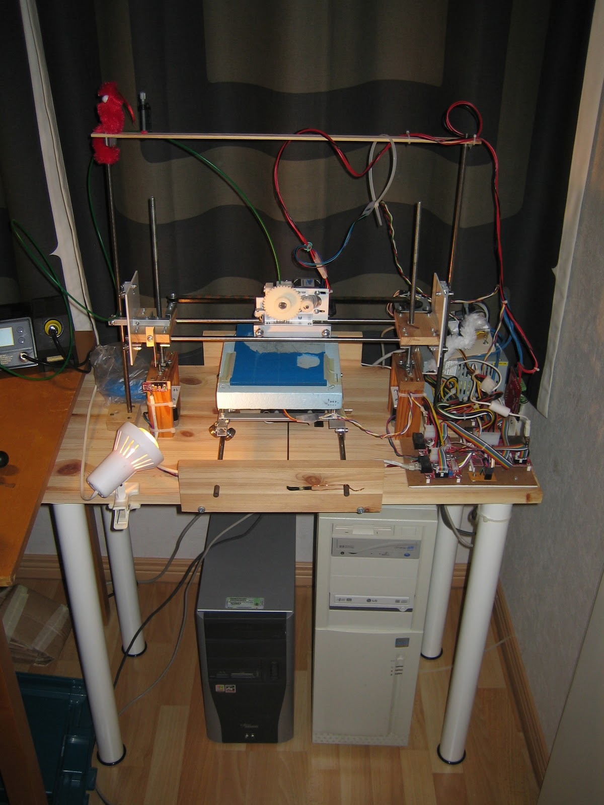
previous post was connected to a new x-carriage using L-shaped aluminium strips and m3 bolts. The x-carriage is the same as the x-carriage made for the makerbot MK4 extruder. I decided to keep the old carriage with MK4 extruder untouched to be able to switch back an forth between extruders easily by just replacing the whole x-carriage. Extruders not being the most reliable part of the 3D printers...
I used a new nozzle and PTFE insulator from mendel-parts.com. Though this nozzle and insulator are meant to be used as in standard mendel fashion (glued at the insulator), I decided to make the construction a bit stronger. The filament is pushed down with quite a bit of force into the nozzle and when the insulator is getting warm it may fail. To prevent the downward force to be taken up by the insulator most modern extruders have some kind of support connecting the nozzle to the rest of the extruder above the insulator. I used a thinned M6 nut on the nozzle and stip of alumium attached by 2 long m3 bolts to protect the insulator.

The aluminium strip is not ideal as it conducts heat too well. The contact area between the nut and the aluminium is kept as small as possible and there is a bit of kapton tape in between; the nozzle does not touch the aluminium.  A new design for the mendel extruder which can be found in the wiki uses a piece of PEEK, but I did not have that available. Below the aluminium strip a short part of the nozzle is left to put the nichrome wire around and to attach a thermistor. All is electrically isolated with kapton tape. As I did not have proper heat insulation around the hot end of the extruder like in the MK4 extruder and the metal strip is leaking some heat, I see it takes a bit longer for the extruder to warm up properly and the temperature seems to vary more than it used to. This does not seem to hurt the operation and the extruder is working fine. A hose clamp around the insulator is an additional bit of protection, not sure if that is really needed, but it probably won't hurt.

The stepper motor is controlled by a TCA3727 integrated circuit via a separate arduino board. The TCA3727 is quite old and better alternatives can be found, but is works fine. A quick-and-dirty program was written to make the motor turn at a constant speed using full steps. The circuit allows for quarter and eighth step but I did not think that would be necessary; that was a wrong, because while the stepper motor turns at the right speed, it vibrates horribly. Especially since the x-carriage is pulled down by gravity only (no ball bearings under the horizontal metal rods), one full step lifts the carriage an invisible fraction everytime before it falls back. When PLA is extruded in the air and left to flow down, it is visible that the extrusion in not constant but it is a bit thicker for each step. Some more software should fix this later.

The extrusion motor control is not integrated with the rest of the electronics or the rest of the software. I manually start extrusion and the printer software is still sending signals to the MK4 gearmotor, though that is not connected anymore. This works surprisingly well. Of course there are ugly plastic lines from head movements where the extrusion should be off but isn't here an there, but depending on the object to be printed these could be tolerated. Of course this will be fixed later, having precise control over the extruder was one of the reasons for building a stepper controlled extruder in the first place.

So far I used the MK4 extruder only with ABS plastic. The pulley which is used to get a grip on the plastic filament has "teeth" which are quite wide. The ABS was clearly stretched and clear marks of the pulley are visible on the filament. Since PLA plastic is much harder (when cold) than ABS. I did not even try it, though some people did get it to work. The new extruder is using many more, but much smaller "teeth" to get grip on the filament. PLA has the advantage of warping much less allowing larger objects to be made. The largest object made so far with ABS is the big gear on the new extruder. It too is warped a bit, but it is just "flat enough" to work.


Summarizing things that can be improved still on the extruder:
- extruder connected with 2 aluminium strips on each side, a better design should allow that to be just one part
- motor control from 3D printing software. I currently use replicatorG but I have not found how that can be integrated with a stepper controller yet, maybe it is time to switch over to the FiveD reprap software which has inbuild extruder stepper motor control.
- Wiring should be fixed.
- 8th stepping to be implemented.

The extruder works though and printed without issues for more than 2.5 hours in a row on a single object.

Sunday, September 5, 2010

New extruder's first steps.

The new extruder is working! It is not ready yet, but I can show the first picture.

The extruder is mounted on a new carriage built in the same way as the previous carriage. I would like to improve it later still, because I needed 2 sets of aluminium strips when one should have been enough, but it works ok like this. The extruder is kept down by gravity only.

The green key is printed in green PLA. More information to follow.

Tuesday, August 31, 2010

Mk4 extruder fail.

The makerbot MK4 extruder has been working fine as I reported earlier.... until today. While trying to print a small object, the extrusion stopped. The heater was working fine, the extrusion motor was working fine, but the filament was not moving anymore. Closer inspection showed that the ball bearing which is around the axle of the motor had shifted and almost fell out.


This was a reason to take the whole extruder apart to check what was going on inside. When taking the top plate of the extruder and removing the motor, the ball bearing came off... with part of the pulley.


The pulley should look like this (photo from makerbot flickr pool).

The thin flange of the pulley came off and after removing the small shreds of aluminium the flange is running loose around the rest of the pulley. I did put the extruder back together with the loose flange, but the bearing was pushed away again after extruding less than 5 cm and the filament stopped moving again.


I have seen many broken extruders in the blogs, but usually they where related to the insulator leaking, the retainer plate breaking, or the lack of grip on the filament because of the idler wheel slipping away. I did find some references to the same failure (e.g. here), but the best indication that this may not be such an uncommon fault is the fact that Makerbot is selling the pulleys also specifically "if you have broken your pulley"...

It is actually not so surprising that this part breaks. The idler wheel is pushing hardest in the middle of the pulley, so the filament will try to take either inside corner of the pulley to get away from it. This will create a serious sideways force. The flange of the aluminium pulley is only press-fit on the pulley and it looks like it is not strong enough. I guess the solution is to get the new MK5 drive gear upgrade kit which is made of one single piece of stainless steel and it looks much stronger.  Possibly I make something similar myself.

I had already started work on a new "Wade" type extruder, but this is not ready yet. I will try to finnish that asap to get a functioning printer again, but I do want to fix my MK4 too, since having a spare extruder will come in handy someday.


Some parts printed when the pulley was still ok: the Hemi-Demi sphere from thingiverse. These parts:


will make this sphere:


Tuesday, August 24, 2010

New extruder

The makerbot extruder is very good, but I really like Wade's extruder design which is using a stepper motor to push filament into the hot end. Having a stepper motor will give much more control over the extrusion which should help in combating the ugly plastic strings which are drawn between parts of an objects caused by the extruder leaking some plastic after the motor has stopped; a stepper motor can be reversed very quickly and pull the molten plastic back in.

It sounds simple enough to download Wade's design from thingiverse (here) and print it, but currently I am not able to print the largest part. The reason for this is warping. Any design which is larger than about 4 cm is warping so badly that the chance of it coming loose from the raft is about 80%. For larger objects the chance increases and it is double painful there, because when an object is large it usually takes a long time to print and therefore it may come loose after for instance two hours of printing...  Since my repstrap is different from the standard Mendel design (the horizontal rods from the x-axis are further apart), I am not able to use the design without modifying it a bit anyway. I decided to use the most complicated part of Wade's design and print that in ABS, use some 3mm polystyrene plastic sheet for the motor mount and use aluminium L-shaped profiles to attach it to the x-axis carriage.

The  extruder has several parts:
  • The extruder block  - Here I used a modified Wade's extruder block; I will upload it as a derivative to thingiverse later.


  • The extruder idler block  - For this I used Nophead's beefed up version from thingiverse.

  • A motor mount plate - Made of polystyrene having the same layout as Wade's extruder block for the motor but made a bit larger so that it can be fixed with bolts to the modified extruder block
  • A large gear - From Wade's design.
  • A small gear - For this I used Nophead's gear with set screw.


  • Standard 608 ball bearings
  • Aluminium profile and nuts and bolts to keep things together.
The bolt looks like this when inserted thought the extruder block:


The extruder is not ready yet, more information to follow later. I did test how well the hobbed extruder bolt grips the PLA filament (which is much harder than ABS) and it looks very good so far.


Saturday, August 14, 2010

Z-axis

After descriptions of the X and Y axis, the Z axis wants to be talked about too..

The Z-axis consists of:
  • 2 freestanding vertical metal rods
  • 2 separate stepper motors connected to threaded rods with a trapped nut in the x-axis ends
  • 2 different sliding mechanisms connected to the x-axis ends


The repstrap does not have the Mendel threaded rod frame, but is built on a wooden basis. The vertical rods for the Z-axis are free standing, they are not supported at the top. This is another part which was thought to be temporary, but which turned out to be good enough and may be a pemanent solution. A 2 cm thick piece of  hard wood is fixed to the basis and an 8 mm hole is drilled though the wood and halfway though the basis to give the rod a proper chance to stay put.


The 2 rods are connected to eachother with a thin strip of wood to make sure the distance between the rods is the same at the bottom and the top.


Two stepper motors were used for the z-axis when one would have been enough. It was easier to get an extra stepper motor than to get a set of pulleys and a timing belt to be able to use a single motor. So 2 motors were used (temporarily?); electrically the 2 motors are wired in series to the same stepper motor driver. This arrangement does not allow you to get the most power out of your motor (there is plenty of power available) but it makes sure the same current is running though the 2 motors and the the stepper motor driver will not get overloaded. The motors are connected to the threaded rods with a plastic tube which allows some movement to compensate for minor misallignment of the motor shaft and the threaded rod. Since steppermotors should not be loaded too much in the direction of the axle, a ball bearing is fixed in the wooden frame around the motors like this:


The motor is not resting on the basis, it is just very close, to avoid resonance.

The threaded rod is going though trapped nuts in the ends of the x-axis; the top of the threaded rod is not supported. The nuts are hot glued in some pieces of scrap plastic which are fixed with screws which have space to move horizontally. The hot glue is not very stong; this is on purpose. Already in several situations this has saved the printer form self destructing: when the z-axis is lowered too much the nuts will be separated from the plastic and will start to turn, thus stopping further damage.


The sliding mechanism around the vertical rods is close to Mendels, but the amount of ball bearings is less. One single ball bearing on the extreme left of the machine is the only bearing which is keeping the whole x assembly from moving to the right. The next 2 pictures show the arrangement on left (ball bearings in 135+90+135 configuration, allowing only up-down movement) and the right (180+180, allowing up-down and left-right movement).


The horizontal aluminium profile above  is fixed with 2 vertical M3 bolts but it can move in holes which are about 5 mm wide so that the M4 bolt a the top can be used to adjust exactly how tight the ball bearings are gripping the metal rod.


The metal rods of the x-axis are going through the white plastic which is used on both sides to make a very rigid construction and to prevent the x-axis to be twisted.

As usual one printed object at the end of a post. The object is for testing only: a 10 cm long single layer wall thickness cylinder with a diameter of 4 cm. The object shows no bad effects of the free standing z-axis. There are some artefacts visible in the object which should not be there: everytime the printer is starting a new layer, too much plastic is deposited causing some blobs. The comb module in skeinforge will move the position of this point causing it to look like some kind of staircase. I hope something can be done in software to prevent this in the future: